


 İnstagram
 Facebook
How Accurate CAD Conversion Can Reduce Rework in Engineering Projects
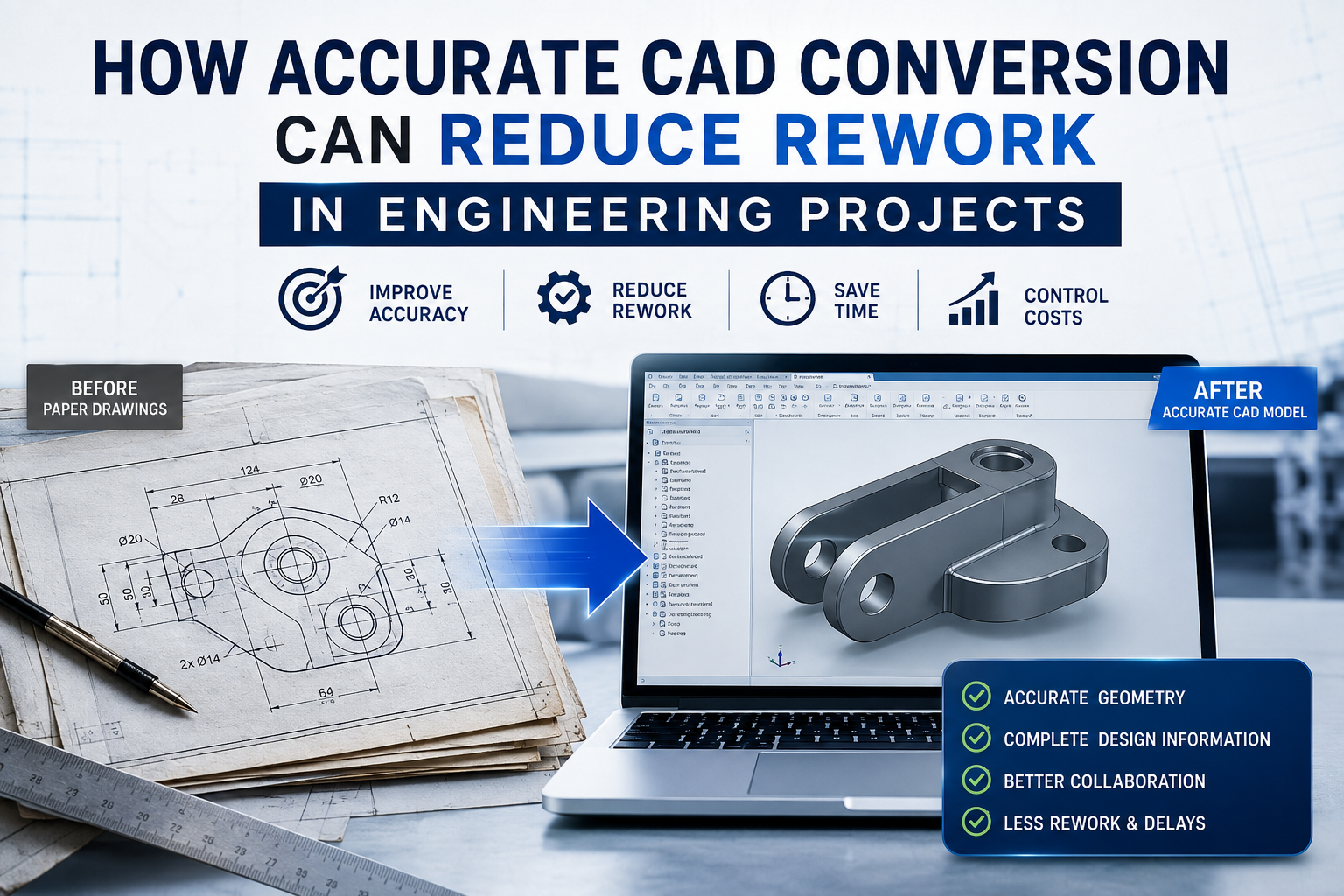
Engineering projects rarely go wrong because of one big mistake. More often, problems build up from small inaccuracies: a missing dimension, an incorrectly recreated feature, an outdated drawing, or CAD data that does not quite match the original design.
When those issues make their way into manufacturing, inspection, or assembly, the result can be expensive rework.
This is where accurate cad conversion services can make a meaningful difference. Converting paper drawings, PDFs, scanned documents, legacy CAD files, or physical parts into reliable digital CAD data gives engineering teams a more usable foundation for design and production.
But CAD conversion is not simply about changing one file format into another. The real value comes from preserving geometry, dimensions, design intent, and other engineering information accurately enough for the resulting data to be used downstream.
What Is CAD Conversion and Why Does Accuracy Matter?
CAD conversion is the process of transforming existing design information into a usable computer-aided design format. Depending on the project, the source might be a paper drawing, raster image, PDF, scanned component, point cloud, or an older CAD file.
The objective is usually straightforward: create an editable digital representation that engineers can modify, analyze, manufacture, or reuse.
The challenge is that engineering drawings contain much more information than lines and shapes.
Dimensions, tolerances, annotations, layers, relationships between features, and other details can all affect how a component is designed and manufactured. If those details are lost or interpreted incorrectly during conversion, the resulting CAD file may look right while still being technically wrong.
That distinction is important.
A successful conversion should produce CAD data that is not only visually similar to the source but also reliable for its intended engineering application.
How Inaccurate CAD Data Creates Rework
Rework often starts when incorrect information is discovered after a project has already moved forward.
Imagine an old mechanical drawing being converted into a 3D model. A hole diameter is interpreted incorrectly. The model passes an initial visual review, but the error is eventually discovered when the component is manufactured.
Now the engineering team may need to:
- Correct the CAD model
- Update manufacturing documentation
- Reprogram equipment
- Reorder or modify components
- Repeat inspections
- Investigate where the discrepancy originated
- Communicate the change to suppliers and other teams
One small conversion error can therefore create work across several stages of the project.
Dimensional and Geometric Errors
Dimensions are among the most important pieces of engineering information contained in technical documentation.
A slight error in a critical dimension can affect clearances, alignment, tolerances, mating components, and overall assembly performance.
Accurate conversion helps ensure that the geometry represented in the digital model remains consistent with the source documentation.
Missing Design Information
A conversion can also create problems when information is omitted rather than changed.
Annotations, tolerances, centerlines, layers, notes, or other supporting information may be important to the people using the CAD file later.
This is why conversion should be treated as an engineering-data task rather than a simple tracing exercise.
Problems During Manufacturing and Inspection
CAD data often travels far beyond the design department.
It may be used for manufacturing, CAM programming, inspection, tooling, simulation, documentation, and supplier communication. NIST's work on model-based manufacturing similarly emphasizes the importance of connecting information across different stages of the product lifecycle and using data to support manufacturing decisions.
If the underlying CAD information is inaccurate, every downstream activity can potentially be affected.
6 Ways Accurate CAD Conversion Reduces Engineering Rework
1. It Preserves Original Design Intent
Legacy engineering drawings often represent years of design knowledge.
When those drawings are converted carefully, the goal is to preserve the information that makes the design meaningful—not simply reproduce its appearance.
A well-converted CAD file can retain important geometry, dimensions, relationships, and annotations so engineers can continue working with the design instead of rebuilding it from scratch.
2. It Helps Catch Problems Earlier
The earlier an error is identified, the easier and cheaper it is generally to correct.
A digital CAD model gives engineering teams an opportunity to inspect geometry, review dimensions, compare features, and identify inconsistencies before the design reaches later stages.
This is especially useful when working with large collections of legacy drawings.
Instead of discovering an issue during fabrication, teams can potentially identify it while validating the converted data.
3. It Improves Design-to-Manufacturing Communication
Engineering projects involve multiple groups, and each group may interpret information differently.
A dependable CAD model provides a common digital reference for designers, engineers, manufacturers, inspectors, and suppliers.
This becomes increasingly important as organizations move toward digital product definition. ASME's Y14.41 Digital Product Definition Data Practices establishes requirements related to preparing and revising digital product definition data, illustrating the importance of managing digital engineering information systematically.
4. It Makes Revisions Faster and More Controlled
One of the biggest advantages of converting legacy information into editable CAD is that future modifications become easier.
Instead of manually editing a paper drawing or recreating geometry every time a design changes, engineers can work directly with the digital model.
That can reduce repetitive work and make design changes easier to communicate.
However, revision control is just as important as editability. The current ASME Y14.35 standard addresses practices for revising engineering product-definition datasets and associated documents, including methods for identifying and recording revisions.
5. It Supports Inspection and Quality Control
Accurate CAD data can serve as an important reference during inspection.
For example, inspection teams may need to compare manufactured geometry against the intended design. If the reference CAD model contains conversion errors, the inspection process itself can become unreliable.
The better approach is to validate the converted CAD data before it becomes the reference for downstream activities.
6. It Makes Legacy Designs Easier to Reuse
Many organizations have valuable engineering information sitting in old drawings, scanned documents, or outdated file formats.
That information may still describe useful products, components, tooling, or assemblies.
Converting it into modern, editable CAD data can make those designs much easier to search, modify, analyze, and manufacture again.
Instead of treating legacy documentation as something that can only be archived, organizations can turn it into a usable engineering resource.
The CAD Conversion Workflow: From Source Drawing to Verified Model
Accurate conversion usually requires more than pressing an import or conversion button.
A structured workflow can help reduce errors and improve the quality of the final deliverable.
1. Review and Prepare the Source Data
The first step is understanding what is being converted.
The source may contain:
- Multiple drawing views
- Dimensions
- Notes
- Tolerances
- Scanned marks or imperfections
- Missing information
- Different scales
- Old drafting conventions
Reviewing these characteristics before conversion helps establish what needs particular attention.
2. Convert or Rebuild the Geometry
The conversion method depends heavily on the source.
A clean vector drawing may require relatively straightforward CAD reconstruction. A scanned physical component can be much more involved.
For scan-to-CAD workflows, Autodesk's current guidance describes a process involving point-cloud or mesh preparation followed by reconstruction using sketches, dimensions, parametric features, or surface modeling. Autodesk also notes that automatic scan-to-CAD conversion is not supported for accurate editable results in the workflow it describes; manual or semi-manual remodeling may be required.
That is a good reminder that automation can speed up conversion, but engineering judgment still matters.
3. Add Engineering Information
Once the basic geometry is created, the CAD file may need dimensions, tolerances, annotations, layers, features, and other information restored or organized.
This step helps turn a basic digital shape into a useful engineering dataset.
4. Validate the Converted CAD File
Validation should compare the new CAD data with the original source.
Depending on the project, this may involve checking:
- Critical dimensions
- Geometry
- Scale
- Hole locations
- Angles
- Feature relationships
- Tolerances
- Annotations
- Overall completeness
The level of checking should reflect how the CAD file will ultimately be used.
5. Perform an Engineering Review
A final review provides another opportunity to catch discrepancies before the file moves downstream.
This human verification step can be particularly valuable for complex parts, poorly scanned drawings, legacy documentation, and designs with tight tolerances.
Why Scan-to-CAD and Legacy Drawing Conversion Require More Than Automation
Automation has made CAD conversion faster, but faster does not automatically mean more accurate.
A computer can recognize geometry and process large amounts of data quickly. It does not necessarily understand why a particular dimension matters or whether an apparently insignificant feature is critical to assembly.
This is particularly relevant when converting physical parts or scans into editable CAD.
Autodesk's April 2026 guidance explains that scan data may need to be cleaned and reduced before being used as reference geometry, and that complex shapes can require surface modeling and manual or semi-manual reconstruction.
The Limitations of Automatic Conversion
Automatic tools can be useful for repetitive tasks, but engineering conversion frequently involves decisions.
For example:
- Is this edge a design feature or a scanning artifact?
- Should this curved surface be modeled as a simple radius or a complex surface?
- Is a dimension missing from the scan?
- Does the reconstructed geometry represent the original manufacturing intent?
- Which features need parametric relationships?
These questions require more than geometric recognition.
Why Verification Still Matters
Verification provides a safety net between conversion and downstream use.
A converted model should be checked against its source before engineers, manufacturers, or inspectors rely on it.
That extra review may seem like additional work, but it is often far less disruptive than correcting an error after manufacturing has started.
Standards and Best Practices That Help Prevent CAD-Related Rework
Standards provide another layer of consistency in engineering documentation and digital product information.
Technical Drawing and Representation Standards
Technical drawings need to communicate design information consistently.
ISO 128-1:2020 provides general principles for the representation of technical drawings, including both 2D and 3D technical drawings and computer-based drawings. ISO's current record shows that the standard was reviewed and confirmed in 2026, so the 2020 edition remains current.
Following appropriate drawing and documentation practices can make source information easier to interpret and convert accurately.
Digital Product Definition and Model-Based Engineering
Engineering is increasingly moving toward digital product-definition approaches in which the CAD model itself carries a significant portion of the information required throughout the product lifecycle.
ASME Y14.41 specifically addresses digital product definition data practices and the preparation and revision of digital datasets.
The larger benefit is consistency: design information can become easier to share and use across engineering, manufacturing, inspection, and other functions.
Revision and Change Management
Accurate geometry is only part of the equation.
Teams also need to know which version of a CAD file is current.
Poor revision management can lead to a different kind of rework—where everyone is working from accurate information, but not the same information.
ASME Y14.35-2025 addresses revision practices for engineering product-definition datasets and associated documents, including identifying and recording revisions.
How to Choose a CAD Conversion Partner
Not every CAD conversion project has the same requirements.
A simple 2D drawing conversion may be very different from rebuilding a complex mechanical component from scan data.
When evaluating a conversion provider, consider the following.
Engineering Accuracy and Quality Control
Ask how the provider verifies converted files.
A strong process should include some form of comparison, quality checking, or engineering review rather than relying solely on automated conversion.
Software and File-Format Compatibility
Make sure the provider can deliver files compatible with the CAD systems used by your engineering and manufacturing teams.
Compatibility matters because a technically correct conversion is not particularly useful if the final file cannot be properly edited or integrated into your workflow.
Industry and Engineering Experience
Experience with engineering drawings and CAD software is valuable, but industry knowledge can matter just as much.
A provider familiar with mechanical design, manufacturing, fabrication, architecture, or another relevant discipline is more likely to understand why particular details matter.
Clear Deliverables and Revision Procedures
Before starting a project, clarify:
- Required file formats
- Layer and feature organization
- Naming conventions
- Required level of detail
- Accuracy requirements
- Validation procedures
- Revision expectations
Clear requirements at the beginning can prevent misunderstandings later.
The Business Impact of Reducing CAD-Related Rework
The value of accurate CAD conversion extends beyond the engineering department.
When design information is dependable, downstream teams have a stronger foundation for their own work.
That can contribute to:
- Fewer design corrections
- Less manufacturing disruption
- Faster engineering revisions
- Reduced duplication of work
- Better supplier communication
- More efficient inspection
- Greater reuse of legacy designs
- More predictable project schedules
NIST's model-based manufacturing research highlights how information from different product-lifecycle stages can influence decisions elsewhere in the manufacturing process. Its work also focuses on measurement, verification, validation, and connecting manufacturing capability information with operational decision-making.
In other words, accurate digital engineering data can have value well beyond the CAD workstation.
Conclusion
CAD conversion may look like a technical file-conversion task, but in engineering projects, accuracy has much bigger consequences.
When drawings, scans, PDFs, or legacy CAD files are converted incorrectly, errors can travel into design reviews, manufacturing, inspection, assembly, and documentation. By the time the problem is discovered, correcting it can require significant time and money.
Accurate conversion helps break that chain.
By preserving design intent, maintaining important dimensions and engineering information, supporting controlled revisions, and validating the final CAD data before it moves downstream, engineering teams can reduce avoidable rework and make better use of their existing design information.
The key is to think beyond simply creating a CAD file. The goal should be to create reliable engineering data that people can confidently use throughout the project lifecycle.

 Türkçe
 English
 Arabic
 Russian